Pulse processing tutorial
This article will explain pulse measurement processing and provide an example of creating pulse processing model
Introduction
Pulse measurements may be used to measure
- flow such as water, gas or electricity
- speed such as rotating shafts
- position such as position of linear and rotary actuators
- level such as liquids in tank
- count e.g. products at the end of a production line.
Pulse signal is typically handled by the device connected to the sensor. The actual pulse is counted by the device to increasing pulse counter that is provided as pulse measurement. Our example starts from the pulse counter. Pulse counter is not usable for application as such, because it is just all the time increasing number. Our example pulse processing is used to change the pulse counter measurement to human understandable time series signals.
The goal of this example tutorial is to show a simple way to create pulse processing system with our engineering tooling. Our example contains an Equipment Model to define the signals and parameters, and calculation to implement the pulse processing logic.
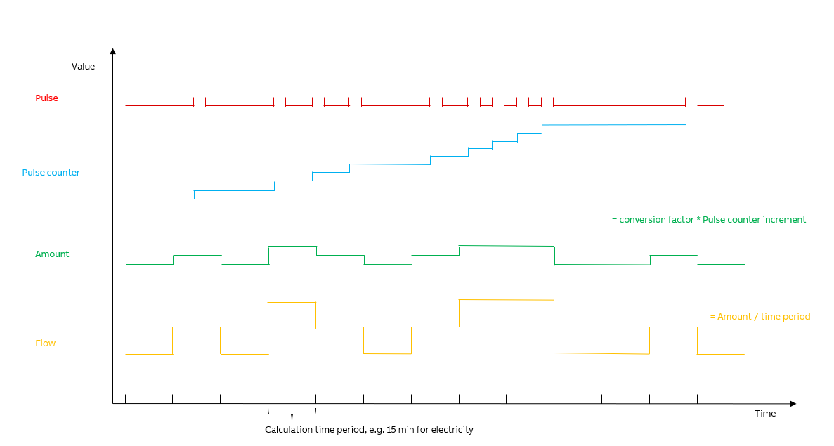
In our example we will create an energy meter that measures energy usage of a relatively large electric motor. The picture below shows the key signals of our pulse processing example and these are PulseCounter, Amount and Flow.
Defining Equipment Model
First step of building pulse processing system is to plan and write down an Equipment Model. For this example we have created one model called ABB.AbilityHistory.Examples.PulseProcessing and properties for it as needed.
Equipment Model definitions and properties are shown in the tables below.
Model definition
| Name | Base | Abstract | Class Name |
|---|---|---|---|
| ABB.AbilityHistory.Examples.PulseProcessing | - | No | Path_ABB.AbilityHistory.Examples.PulseProcessing |
Model hierarchy
ABB.AbilityHistory.Examples.PulseProcessing
└── PulseSensor
Model properties
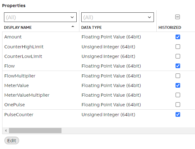
After defining the model hierarchy, we will create properties for it. As shown in the table below, we are only historizing values of Amount, Flow, MeterValue and PulseCounter. Other properties are parameters of our value definitions.
| Property | Data type | Unit | Historized | Description |
|---|---|---|---|---|
| Amount | Floating Point Value (64bit) | KWh | Yes | Identification of the variable for engineering unit value aggregate of the pulse input. |
| CounterHighLimit | Unsigned Integer (64bit) | High limit of the pulse input counter. | ||
| CounterLowLimit | Unsigned Integer (64bit) | Low limit of the pulse input counter. | ||
| Flow | Floating Point Value (64bit) | kW | Yes | Identification of the variable for time derivation aggregate of the pulse input. |
| FlowMultiplier | Floating Point Value (64bit) | Coefficient to convert Flow to engineering units. 1 = units per second. | ||
| MeterValue | Floating Point Value (64bit) | Yes | Identification of the variable for sensor display value aggregate of the pulse input. | |
| MeterValueMultiplier | Floating Point Value (64bit) | Multiplier for identification of the variable. | ||
| OnePulse | Floating Point Value (64bit) | Coefficient to convert pulse input value to engineering units. | ||
| PulseCounter | Unsigned Integer (64bit) | Yes | Pulse value received from pulse sensor. |
Equipment Instance
Instance hierarchy and path
We have created one instance for this model and named it PulseSensor. In our model this represents the device where pulse is being read and measured from. The full instance path is DemoFactory.PulseSensor. We may access properties through our PulseSensor instance and all property values will be defined by calculation, read from device or read from variables. We will determine these in our example calculation chapter.
ABB.AbilityHistory.Examples.PulseProcessing
└── PulseSensor
Creating Equipment Model in Engineering UI
Now that we have defined Equipment type hierarchy, properties and instances, we can configure these with the Engineering UI web application.
- If you need a reminder of how to connect, please see Engineering UI
- If you need further information on our Equipment Model concept, please see Equipment model
- If you need further information on the concept of Information Meta Model, please see Information model
Creating Equipment classes, properties and instances
In the Engineering UI we created Equipment Models under Information Model > Equipment Classes and Instances under Information Model > Equipment Instances.
As shown above for our example model, we define one class (ABB.AbilityHistory.Examples.PulseProcessing) and one instance with relevant properties.
Creating Properties
For our example model, we defined the following properties:
- Name
- Data Type
- Historized
- Category
- Description
- Compression Method: We use Quantization Lane Compression.
- Target History: CurrentHistory is suitable for us for this example with changing current values that require updating. Please find further information on CurrentHistory and StreamHistory definitions here.
- In advanced settings of each property we also set the properties as "discrete" as needed.
Please be advised when applying this to your customer system, that in order to get accurate values, it is important to define the properties as discrete and use the right compression method (no-compression). This is important for filter use as well in user interface monitors. We will discuss filter use later on in this article.
Other definitions we left as the default settings.
When editing property definitions, choose each option carefully to avoid changing them later during the process.
Creating Equipment Instance
After defining properties we can move on to creating our PulseSensor instance.
Creating instances correctly requires at least the following information (our model definitions as examples) :
- Name (e.g. PulseSensor)
- Parent (e.g. DemoFactory)
- Process Path (e.g. DemoFactory.PulseSensor)
- Equipment model (e.g. ABB.AbilityHistory.Examples.PulseProcessing)
Always remember to commit changes to save them.
Now that we have successfully created Equipment models and instances, we can move on to our coding tool that is called calculation catalog.
Overriding property attributes
In Engineering UI it is possible to override EquipmentPropertyInfo attributes, if needed. There are a few simple steps to do so and we have made a quick user guide under our Equipment Model article. Please find further information here.
More information on Equipment model?See theory and other example case: Equipment model
Calculation for Pulse processing example
In Engineering UI we created our code in our Calculation Catalog (found in Applications > Calculations > Catalog).
In our example we created one calculation that will give an example how pulse processing values may be calculated. In our calculation we define values for PulseCounter, Amount, Flow and MeterValue.
Trigger
For our calculation we use 1 minute scheduler so that calculation will run periodically and we receive data every minute.
Further information on different triggers may be found in our Engineering UI tutorial on calculation settings section.
Data Mapping
To consider when defining data mapping:
- Name: Name should be recognizable yet not include equipment model or calculation name. These will give you errors when defining code.
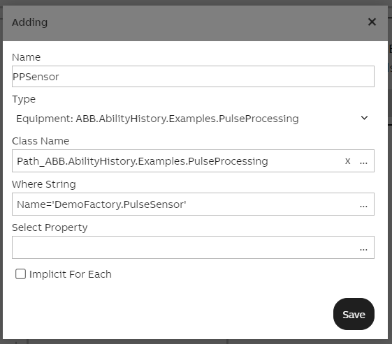
- Type: From dropdown menu we can choose the Equipment model we want to use.
- Class Name: This should include the path for the equipment class. In our example case this would be Path_ABB.AbilityHistory.Examples.PulseProcessing.
- Where String: When referring to all properties and instances we include _Name= ' ' _here. In our example case this would be
Name= 'DemoFactory.PulseSensor'. With this, our code will iterate through all our Equipment model properties and instances via the name we have defined first in data mapping settings. An example is given below with our pulse processing settings. - Select Property: If we only use a single property in calculation, that may be defined here.
For data mapping we defined the equipment model as the output parameter. Remember to include Path_ name when defining Class Name and Name=' ' when referring to all properties and instances of the equipment model.
Please note: You may also create code first and then add parameters in the code editor window.
Creating the code
The calculation code contains the actual logic and we use C# as the coding language. The calculation code is a class including a single method. The code reads the existing time-series and writes the generated time-series using input and output parameters.
Our example code is presented below. PPSensor.in the beginning refers to the output property name given when setting output parameter. You may choose a name that is most convenient, but keep in mind this may not include the equipment model name or the calculation name.
As the code shows we have set so that our PulseCounter increments by one with each period.
public void Calculate(CalcEquipment_ABB_AbilityHistory_Examples_PulseProcessing PPSensor)
{
     if (PPSensor.PulseCounter.Last.Invalid)
     {
        PPSensor.Amount.WriteValue(0, DefaultPeriod.Start, cValueStatus.Invalid);
        PPSensor.Flow.WriteValue(0, DefaultPeriod.Start, cValueStatus.Invalid);
     }
     else
     {
        ulong counterIncrease = PPSensor.PulseCounter.Last.Value - PPSensor.PulseCounter.GetLast(-1).Value;

        if (counterIncrease < 0)
			   counterIncrease += PPSensor.CounterHighLimit - PPSensor.CounterLowLimit + 1;

   		  double amount = counterIncrease * PPSensor.OnePulse;
	   	  PPSensor.Amount.First = amount;
		    PPSensor.Flow.First = amount * PPSensor.FlowMultiplier;
		    PPSensor.MeterValue.First = PPSensor.PulseCounter.Last.Value * PPSensor.OnePulse;
		 }

}
In the code we use an if-else statement to avoid calculating invalid values and to avoid exceptions. In the code we define values for Amount, Flow and MeterValue. Other Equipment Model properties are parameters for our calculations which values we have defined separately for example purposes.
After applying the code and other settings, the calculation pop-up window may be closed and calculation should start running.
More information on calculation tool?See calculation tool documentation: Concepts
See tutorial on how to use calculation tool in Engineering UI: Creating Calculation
User Interface: Trend Monitor
Lastly to implement user interface to industrial application or solution, we will use our web browser tool View to create desktop like trend for our Pulseprocessing example.
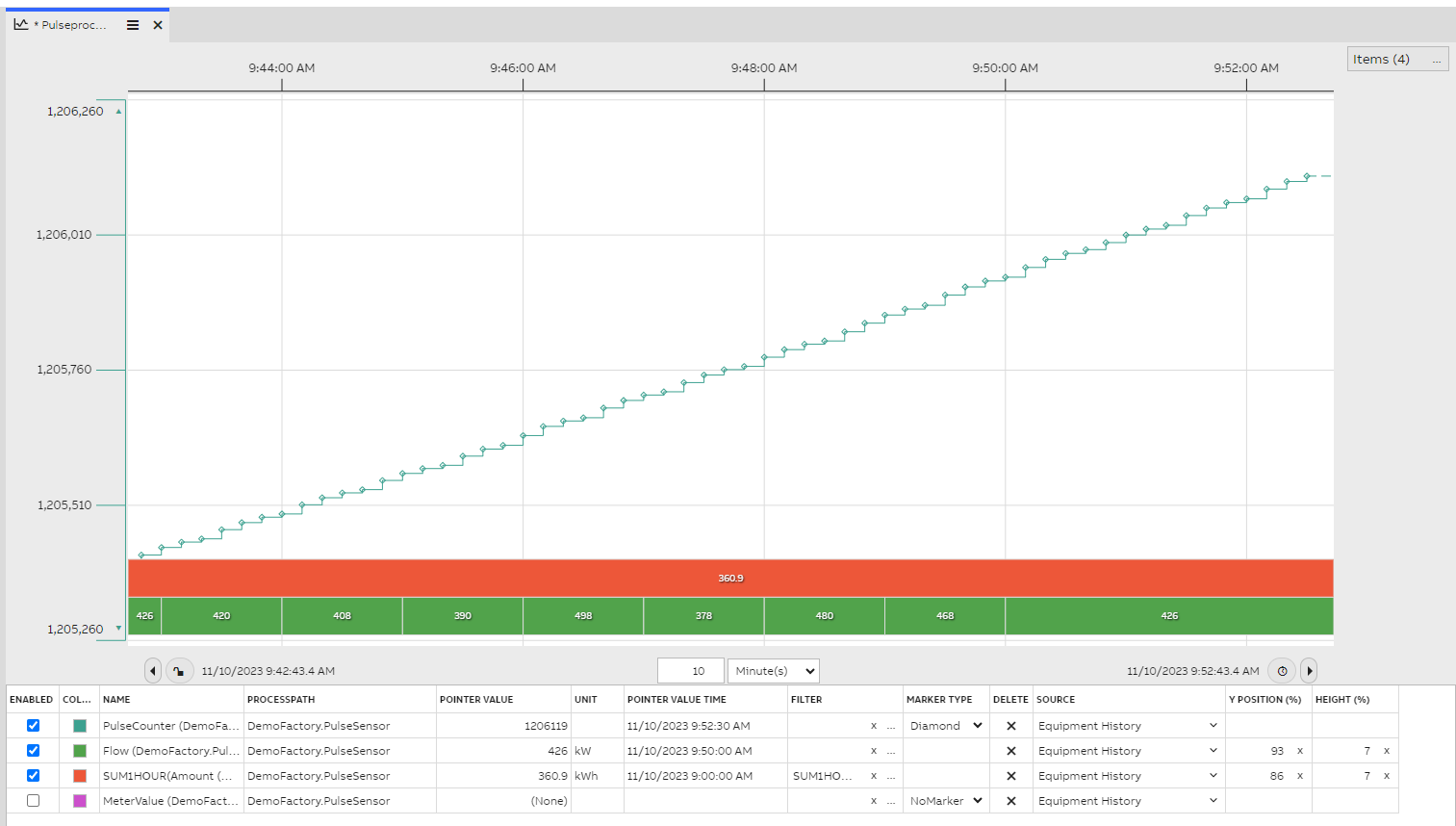
The picture below demonstrates our trend monitor that allows us to visualize changes in our pulse processing example. As shown on the chart, we use SUM1hour filter for our Amount value to see energy consumption within an hour. We have also set Flow and Amount as type Gantt on the chart to monitor value changes easier.
Further information on user interface?Please find further information on filters under Processing data > filters and Time Series > Aggregates and Filters.
Please find Trend monitor tutorial here.
Please find user interface documentation with dashboard editor and step-by-step guide under Concept.
Further information on most commonly used widgets you may find under Standard Widgets.
Step by step Video TutorialWe have created a video tutorial where we discuss and show each step of our pulse processing example. We aim to give good insight on how to to easily create your own pulse processing functionality with our engineering tooling. On the video we first go briefly over the concepts and after show in detail how we created the equipment model and calculations for our pulse processing example. We further show how a trend monitor works in practice and how to tailor this example for your system needs. This video includes insights on how to for example use filtering and how to override property attributes on an instance level.
Updated 9 months ago